Saturday, March 2, 2013

Torque and P-Factor Explained:
Part 1 - Torque Reaction

To the pilot torque is the left turning tendency of the airplane is made up of 4 elements which cause the plane to twist around at least one of the airplane's three axis. (described in an earlier post.

These 4 element are as follows:
1. Torque reaction from engine or propeller
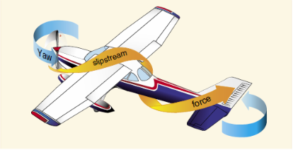
2. Corkscrew effect
3. Gyroscopic action of the propeller
4. Asymmetrical loading of the propeller (P-factor)

This post will only discuss the first element, and the other three will follow in three separate posts.
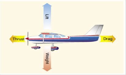
TORQUE REACTION

This reaction involves Newton's Third Law of Physics - which states that for every action there is an equal and opposite reaction. Which translated to planes means that as the internal engine and propeller are rotating in one direction, an equal force is trying to rotate the aircraft in the opposite direction.

As you can see from the picture below, the propeller is turning in one direction labeled as "action", while the plane wings are rotating in the opposite direction labeled "reaction." Also note that the wings are trying to lift up on one side and down on the other.

Photobucket

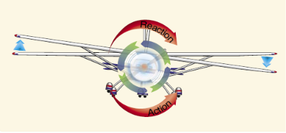
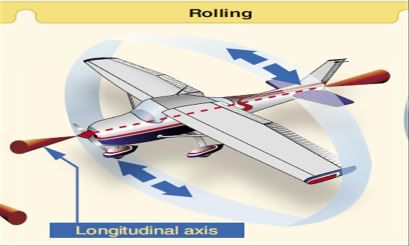
When the airplane is air born, this force is acting on the longitudinal axis, tending to make the airplane roll. Today's planes are designed with an engine offset to counteract this effect of torque.

When the plane is on the ground during takeoff roll, an additional turning tendency is induced by this torque reaction. As the left side of the plane is forced down, it is putting more weight on the left main landing gear. This effect results in more ground friction or drag, more on the left than the right causing even more turning to the left.

The extent of this increase depends on a few variables:
1. Size and horsepower of engine
2. Size of propeller and RPM
3. Size of the aircraft
4. Condition of the ground surface.

Next blog will cover Corkscrew Effect. Please tune in for more.

Torque and P-Factor Explained:
Part 2 - Corkscrew Effect

Continuing on with Part 2 of a 4 part series.
CORKSCREW EFFECT

The high speed rotation of the propeller gives a corkscrew or spiraling rotation to the slipstream, At high propeller speeds and low forward speed or motion of the plane (as in take offs and approaches to power-on stalls), this spiraling rotation is very compact and exerts a strong side ward force on the vertical tail surface.

Look at the picture below. The propeller causes a slipstream over the plane and it then exerts a force on the left side of the vertical tail surface. This then pushes the tail surface to the right and the opposite reaction is that the nose goes to the left or Yaws to the left about the aircraft's vertical axis.

Photobucket

As the forward speed increases, this spiral effect elongated and becomes less effective. This corkscrew flow also causes a rolling motion around the longitudinal axis.

Notice that this rolling moment caused the corkscrew is to the right, while the rolling effect caused by torque reaction (part 1 ) is to the left - in effect one may counteract the other.

Come back for Part 3 Gyroscopic Action. See you then.

Torque and P-Factor Explained:
Part 3 - Gyroscopic Action

GYROSCOPIC ACTION


This is the third part of a 4 part series.

All applications of a gyroscope are based on two fundamental properties : rigidity in space and precession. We are only interested in precession for this discussion.


Precession is the resultant action of a spinning rotor when a deflecting force is applied to its rim.

Any time a force is applied to deflect a propeller, the resulting force is 90 degrees ahead of and in the direction of the rotation, causing a pitching moment, a yawing moment, or any combination of the two.


Photobucket
Raising tail produces gyroscopic precession


It is said that, as a result of this action, any yawing around the vertical axis results in a pitching moment, and any pitching around the lateral axis results in a yawing moment.

To correct for the gyroscopic action effect, it is necessary for the pilot to properly use elevator and rudder to prevent undesired pitching and yawing.

Torque and P-Factor Explained:
Part 4 - Asymmetric Loading

ASYMMETRIC LOADING (P-FACTOR)

When an aircraft is flying with a high angle of attack (AOA), the "bite" of the downward moving blade is greater than the "bite" of the upward moving blade. This moves the center of thrust to the right disc area, causing a yawing moment toward the left around a vertical axis.

When the plane is flying at the same high angle of attack (the angle of the plane relative to the wind which is coming in at it), the downward moving blade has a higher resultant velocity, creating more lift than the upward moving blade.

See picture below. When the plane is at a low AOA the load on upward and downward moving blades are equal. But as the second picture shows, at a high AOA, the load on the downward blade is higher than that of the upward moving blade. Both instances the wind is hitting the propeller from the front.

Photobucket


Since the propeller is an airfoil, an increased velocity means increased lift. The down swinging blade (viewed from the rear) has more lift and tends to pull (yaw) the aircraft's nose to the left.

The effects of each of the 4 elements has a different value with changes to the flight situation. When the plan is climbing, will be different than when the plane descending. It also varies with each different aircraft, airframe, engine, or propeller combinations. The pilot in order to maintain flight control, must use the controls to compensate for these varying values.

Wednesday, February 20, 2013

Types Of Drag

As you may remember drag is one of the Four basic fundamentals of flight. But as the title suggests there are different types of drag. Not too get too detailed in this blog, there are at 2 main types of drag: parasite and induced drag.

Remember that drag is the force that resists movement of an airplane through the air. Parasite drag is so named because it in no way functions to aid in flight, while induced drag, is the result of an airfoil (wing) developing lift. Let's look at each a little closer.

PARASITE DRAG
Parasite drag is comprised of all the forces that work to slow the plane down, and as mentioned earlier does not play in the production of lift. There are 3 types of parasite drag: form drag, interference drag, and skin drag.

1. Form Drag
Form drag is the portion of parasite drag generated by the aircraft due to its shape and airflow around it. Examples, include engine cowlings, antennas, and aerodynamic shape of other components.

2. Interference Drag
Interference drag comes from the intersection of air streams that creates eddy currents, turbulence, or restricts smooth airflow. For example, the intersection of the wing and the fuselage at the wing root has significant interference drag. It is also highest when two surfaces meet at perpendicular angles.

3. Skin Friction Drag
Skin friction drag is the aerodynamic resistance due to the contact of moving air with the surface of the aircraft. No matter how apparently smooth a surface appears, has a rough, ragged surface when viewed under a microscope. The actual speed at which the air molecules move depends upon the shape of the wing, the stickiness of the air through which the wing or airfoil is moving, and the compressibility.

INDUCED DRAG
In level flight the aerodynamic properties of a wing or rotor produce a required lift, but at the expense of a certain penalty. Induced drag is the name of the penalty. Induced drag is inherent whenever an airfoil is producing lift, and this type of drag is inseparable from the production of lift. It is always present of lift is produced.

Whenever an airfoil is producing lift, the pressure on the lower surface of it is greater than that on the upper surface (Bernoulli's Principle).

In the area of the wing tips, there is a tendency for these presures to equalize, resulting in a lateral flow outward from the underside to the upper surface. When viewed from the tail, vortices from the wing tips trail behind the airfoils. This also creates a downwash flow behind the wing's trailing edge. In simple terms, this downwash flow, in a sense, is the induced drag that is created when the plane has produced lift.

Saturday, February 16, 2013

3 Axis of Rotation

The axis of an aircraft are three imaginary lines that pass through an aircraft's CG (center of gravity). These axis can be thought of as imaginary axles around which the aircraft turns. They pass through the CG at 90 degree angles to each other.

These three are called the lateral, longitudinal, and vertical axis.

LATERAL AXIS
The axis that passes from wingtip to wingtip is known as the lateral axis. When the plane rotates on this axis, it is pitching up and down. Lateral axis creates a PITCH.

Photobucket

LONGITUDINAL AXIS
The axis that passes from nose to tail is known as the longitudinal axis. In this action the plane does a rolling motion, which is a major component in a turn. Longitudinal axis creates a ROLL.

Photobucket

VERTICAL AXIS
The axis that passes vertically through the CG is the vertical axis. This action causes the plane to yaw, turn left or right without the benifit of "tilting" the plane. Vertical axis creates a YAW.

Photobucket


These names have been adapted to aeronautical terminolgy due to the similarity of aircraft and seagoing ships.

These three actions of the conventional airplane, (pitch, roll, or yaw) are control by three control surfaces. Pitch is controlled by the elevators; roll is controlled by the ailerons; yaw is controlled by the rudder. (more on these surfaces in future lessons). Whenever an aircraft changes its flight attitude or position in flight, it rotates about one or more of these three axis.

Sunday, February 10, 2013

Four Basic Fundamentals of Flight

PhotobucketThere are 4 fundamentals of flight that are imposed on every plane in flight. These four forces acting on an aircraft in straight-and-level, unaccelerated flight are thrust, drag, lift and weight. I will talk about each and explain how these act on the plane. They are defined as follows:

THRUST
Thrust is that force that causes a plane to move forward. It is produced by the power plant/propeller or rotor. It opposes, overcomes, and is opposite of drag. As a general rule, it acts parallel to the longitudinal axis. (More on axis in the next blog).

DRAG
Drag is the rearward, retarding force caused by the disruption of airflow over the wing, rotor, fuselage, and other objects that protrude from the plane. As mentioned earlier, drag and thrust are opposites, and acts rearward parallel to the relative wind.

LIFT
Lift opposes the downward force of weight, is produced by the effect of the air acting on the wings, and acts perpendicular to the flight path.

WEIGHT
Weight is the combined load of the aircraft itself, the crew, the fuel, and cargo. Weight pulls the plane downward because of the force of gravity. It acts opposite of lift, and acts vertically downward through the CG (center of gravity).

Photobucket

In steady flight the sum of all forces is always zero. It does not mean that the four forces are equal. It means the opposing forces are equal to each other and therefore cancel each other out. See figure above.

So in steady, level, flight the sum of all upward forces (lift) equals the sum of all downward forces (weight).

And the sum of all forward forces (thrust) equals the sum of all backward forces (drag).

For an aircraft to move forward thrust must be greater than drag. As the plane continues to move forward and gains speed, then at some point thrust and drag will be equal. Which means that to maintain constant airspeed, thrust and drag are equal. For a constant altitude, lift and weight must be equal.

If thrust is less than drag the plane will slow down, but once thrust is greater than drag , the plane speeds up.